Sensor Watch Accessory Boards (aka Sensor Boards)
You may have noticed that there are no sensors on this board. That is by design: rather than pick sensors for you, the goal is to add a tiny flexible PCB with the sensors YOU want, and interface them over the nine-pin connector. The connector provides the following options for power and connectivity:
- 3V power (3.08 V nominal; can drop to ~2.7V near end of life)
- An I²C interface with built-in pull-up resistors
- Five general purpose IO pins, which can be configured as:
- Five analog inputs
- Five interrupt-capable digital inputs, with internal pull-up or pull-down resistors
- Five digital outputs
- SPI controller (with one spare analog / GPIO pin leftover)
- One UART TX/RX pair (with three GPIO leftover)
- Up to four PWM pins on two independent TC instances
- Two external wake inputs that can wake from the ultra-low-power BACKUP mode
| Pin | Digital | Interrupt | Analog | I2C | SPI | UART | PWM | Ext. Wake |
|---|
| A0 | PB04 | EIC/EXTINT[4] | ADC/AIN[12] | — | — | — | — | — |
| SCL | — | — | — | SCL
SERCOM1[1] | — | — | — | — |
| SDA | — | — | — | SDA
SERCOM1[0] | — | — | — | — |
| A1 | PB01 | EIC/EXTINT[1] | ADC/AIN[9] | — | SCK
SERCOM3[3] | RX
SERCOM3[3] | TC3[1] | — |
| A2 | PB02 | EIC/EXTINT[2] | ADC/AIN[10] | — | MOSI
SERCOM3[0] | TX or RX
SERCOM3[0] | TC2[0] | RTC/IN[1] |
| A3 | PB03 | EIC/EXTINT[3] | ADC/AIN[11] | — | CS
SERCOM3[1] | RX
SERCOM3[1] | TC2[1] | — |
| A4 | PB00 | EIC/EXTINT[0] | ADC/AIN[8] | — | MISO
SERCOM3[2] | TX or RX
SERCOM3[2] | TC3[0] | RTC/IN[0] |
These tiny “sensor boards” have a set outline, and the available area for your electronics is quite small (5.7 × 5.7 × 1 mm). Still, this is plenty of room for an environmental sensor, MEMS accelerometer or magnetometer and a couple of decoupling capacitors. Note that you will likely be limited to QFN and LGA type parts; SOICs are too large, and even SSOP packages are generally too thick. You can find reference designs for several sensor boards in the PCB/Sensor Boards directory in the Sensor Watch repository.
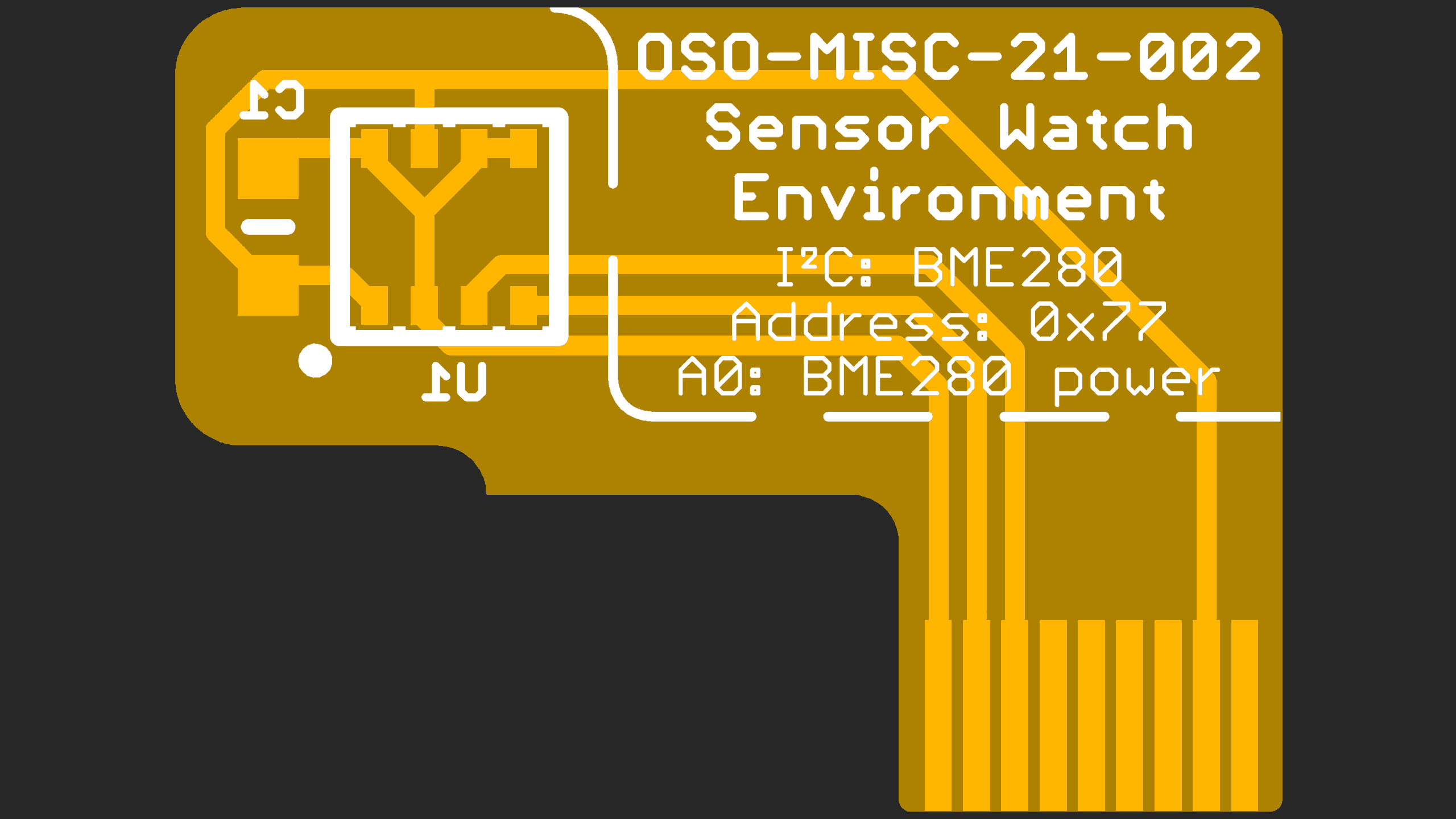
1 - Sensor Watch Accessory Board: Temperature + GPIO
This sensor board shipped to all Sensor Watch Crowd Supply backers, and shipped as a standalone upgrade for several years. It is no longer available, as the new Sensor Watch Pro boards have a temperature sensor built in.
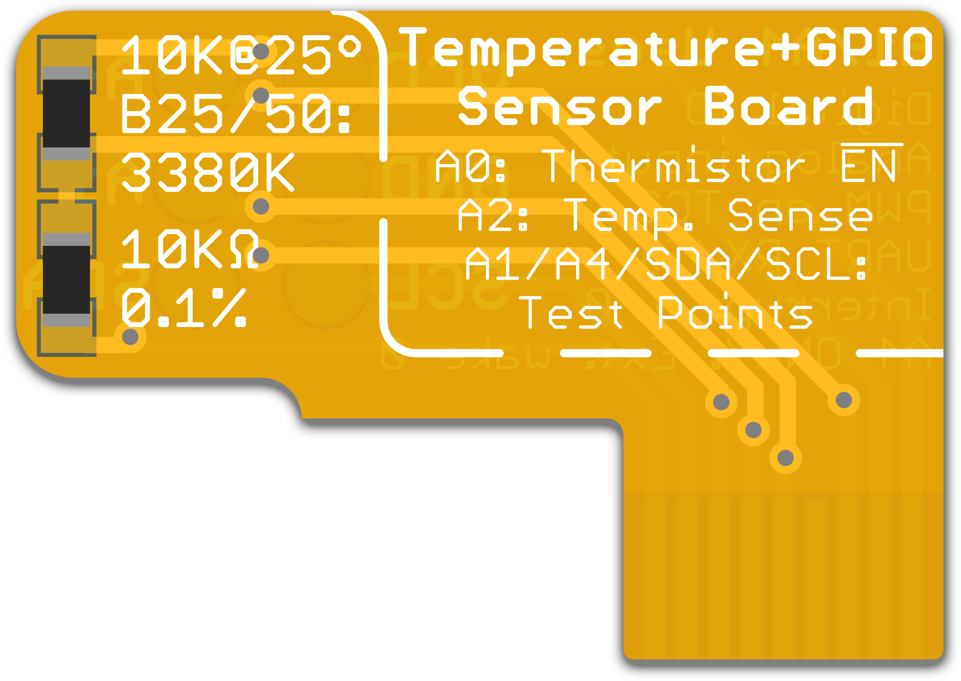
Temperature
The Temperature and GPIO board includes two passive components on the front, a very precise 10 kΩ resistor and a 10 kΩ thermistor, that together form a voltage divider. While the resistance of the 10 kΩ resistor stays very close to 10 kΩ at all temperatures, the thermistor’s resistance goes down as the temperature rises, and goes up as the temperature falls. This changes the voltage that’s measured at the middle of the voltage divider, and with some clever math, we can turn that voltage into a very precise temperature reading.
While the watch library’s thermistor driver is preconfigured with all required parameters for this calculation, we’ll repeat them here for completeness:
- The resistor has a value of 10 kilo-ohms with a tolerance of 0.1%
- The thermistor has a nominal value of 10 kilo-ohms at 25° C, and a B coefficient of 3380K
GPIO
In addition, this sensor board breaks out test points on the underside for six nets: power and ground, the I2C pins SDA and SCL, as well as two GPIO pins, A1 and A4. It will be fiddly, but you can solder fine enamel wires to these test points to connect other kinds of gadgets to your Sensor Watch, whether to test out possibilities for future sensor boards or to bodge in a device with additional functions you want.
Note that if you solder to these test pads, you must cover the five test points on the Sensor Watch board with tape! It’s possible for the solder bumps you create on the underside of the sensor board to touch the main Sensor Watch board, so you must electrically isolate them with tape.
The A1 and A4 pins are very versatile. You can use these two pins as:
- General purpose digital IO to drive a low current device like a sensor or LED
- Analog inputs to read an analog value from a circuit like a phototransistor
- PWM output (they are both on the same TC3 peripheral)
- Input to the TC3 counter peripheral for frequency measurement
- UART transmit (A4) and receive (A1)
- External interrupt inputs
In addition, you can use pin A4 as an external wake interrupt, which can wake the watch from the ultra-low-power BACKUP mode.
2 - Sensor Watch Accessory Board: Accelerometer
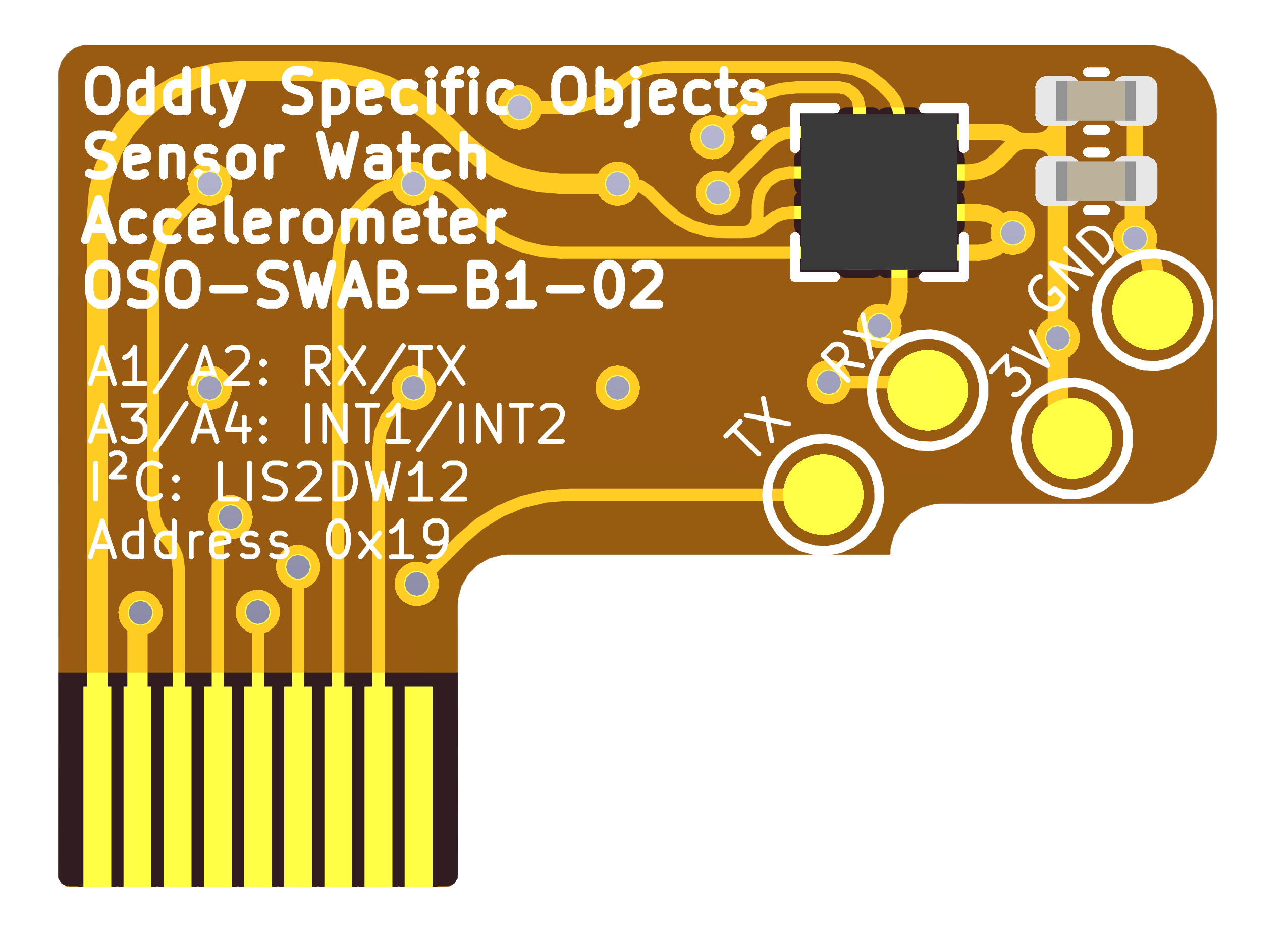
This sensor board shipped to all Sensor Watch Pro Crowd Supply backers. It is also available for separate purchase at the Sensor Watch Pro page on Crowd Supply.
Accelerometer
The accelerometer sensor board includes one active component: the LIS2DW12 high-performance ultra-low-power 3-axis “femto” accelerometer from STMicroelectronics. See the data sheet (PDF link) for details, but in short, it has a configurable output rate from 1.6 Hz to 1600 Hz and two interrupts for a variety of conditions including tap detection, orientation change, and freefall, as well as a status output indicating whether the device is stationary or in motion. All of these interrupts come with configurable thresholds and durations.
While you can do a TON with this sensor, Second Movement configures it to be as low-power as possible: at boot, the accelerometer is set to its low-power (not high-performance) mode, and then it is configured for stationary/motion detection. It’s configured to output this state on pin A4: if pin A4 reads high, the accelerometer is still; if A4 reads low, the accelerometer has recently experienced a high pass filtered acceleration event of >1g on one of its axes.
Then it’s powered down, not to be activated unless a watch face requests it. A watch face can request the accelerometer via two functions: movement_set_accelerometer_background_rate and movement_enable_tap_detection_if_available. To help understand the power impact of thesr options:
- With the accelerometer powered down, as it is at boot, the accelerometer sensor board is consuming an additional 0.05 µA when compared to a board without the sensor installed.
- Calling
movement_set_accelerometer_background_rate with a background rate of 1.6 Hz adds <1 µA of power consumption. - Calling
movement_enable_tap_detection_if_available adds about 150µA of power consumption. As such, tap detection should only be enabled briefly, and paired with a call to movement_disable_tap_detection_if_available.
Currently three watch faces make use of the accelerometer:
- The Activity Logging face will enable the accelerometer at a slow 1.6 Hz sampling rate at boot, and keep there indefinitely in the background. It will then log any consecutive minutes where pin A4 read low. In my experience, this is adequate to capture jogging workouts.
- The Accelerometer Status face displays the state of pin A4: active or still. If the accelerometer was on in the background, it will leave it at that sampling rate; if it was off, it will enable it at 1.6 Hz while the watch face is on screen. This watch face also allows you to change the threshold from 1 g to something else via a long press of the ALARM button.
- The Countdown Timer face will enable tap detection for three seconds when the face comes on screen. You can tap the watch to increment the number of minutes you want to count, and each tap will extend tap detection for another three seconds. Tap detection will be disabled after this timeout, or when the wearer presses the ALARM button to start the timer.
All of these functions return a boolean that indicates whether the operation was successful. If they return false, that means that an accelerometer board was not present; you may want to either update your UI to reflect this condition, or include logic to skip your watch face if the accelerometer is critical for your use case.
UART
In addition to the accelerometer, this sensor board also breaks out test points on the underside for two signals, A2 and A1, as well as power and ground. It will be fiddly, but you can solder fine enamel wires to these test points and run them out of the watch case, which will allow you to talk to the watch over UART. This could be useful if you are interested in streaming acceleration data out of the watch.